Of all the gallant ships in the US Navy during WWII, the USS Enterprise should have been on the top of the list to be preserved. Remarkably, the fate USS Enterprise, CV-6, was to become nothing more than scrap. It has been said that the Enterprise, more than most ships, possessed a soul. Indeed, as a final testament to this fact, as the USS Enterprise had been reduced to nothing more than its keel, one of the ship’s most famous residents, Admiral William F. Halsey, died. Sadly, the only representations of this famous ship are photographs, paintings, and models.
The Enterprise was launched in 1936 and was one of three ships that formed the Yorktown Class of carriers. Along with her sisters Yorktown and Hornet, these ships were the vanguard of the US carrier force during the early stages of the Pacific war. They were also the precursor to the very successful Essex class carriers that would follow. With the exception of the battle of the Coral Sea, Enterprise would participate in every major naval battle of the Pacific campaign and would become the most decorated ship of WWII.
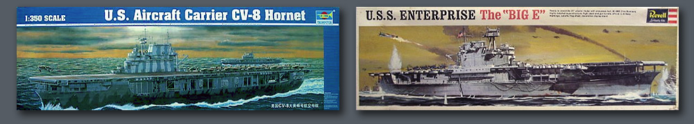
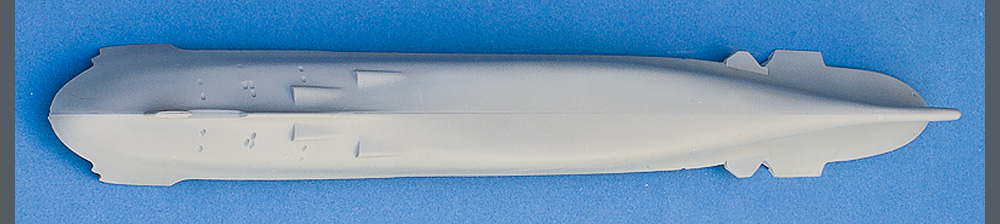
To date, there has been no injection kit of the Enterprise in 1/350th scale. The only alternative available in an injection kit is to convert the Trumpeter Hornet. The Trumpeter Hornet is an extremely poor effort. While this may seem like harsh criticism, you need only compare the hull shape of the Trumpeter kit with that of a 1967 Revell “box scale” release. The inexpensive Revell release does an excellent job at capturing the graceful hull lines of the Yorktown class. On the other hand the Trumpeter kit has all the subtlety of a tanker. There was no lack of documentation when the Trumpeter model was designed and produced using more advanced tooling techniques. The shape difference between these kits really comes down to the fact that there were real craftsmen with skilled eyes shaping the pattern for the Revell kit. The Trumpeter hull looks like it was CAD’ed by some fellow who was designing CD cases the week before and no one cared enough, or knew enough, to realize that it was completely wrong. This is why I believe a new kit does not always translate into a better kit. I usually make an attempt to restrain myself from making such critical remarks regarding a kit, but I am puzzled that a kit of this size, requiring larger than average tooling and expense, would be done with so little care.
I originally adopted the belief that the Trumpeter hull was “not that bad” and it could be adequately corrected. I started construction with an approach that I thought would correct the problem. A copy of my original beginning effort can be seen here and may be of interest to anyone still holding that belief. However, my personal recommendation now is to stay away from this kit unless you plan to waterline it at the level of the hanger deck. It is hard to rationalize constructing a model ship based on the initial premise that “no one will notice that the hull is wrong.” Rather takes the fun out of it. The Enterprise is too important of a ship, and having known several veterans who served aboard her, I feel a personal obligation to create a more accurate representation.
The significance of the Yorktown class hull form is explained by Norman Friedman as he discussed planning for torpedo protection:
“The only way was to accept a much fuller midships section (coefficient 0.95 instead of 0.89) with the consequent increase in required power and machinery weight, which would be unpleasant in a ship limited so tightly by treaty. In this way the outer compartment of the protective system could be extended to within 4 feet of the bottom of the ship. An incidental problem was that, in order to get a fuller midships section, the designers had to take volume out of the ends of the ship, which resulted in the finest-ended ship in the navy.”
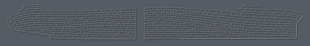
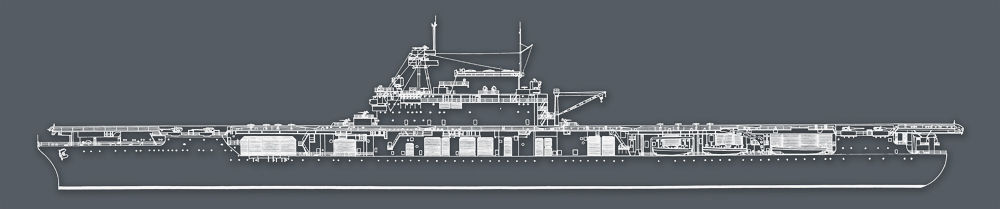
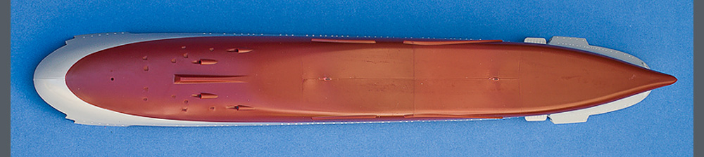
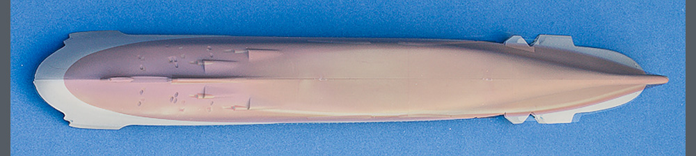
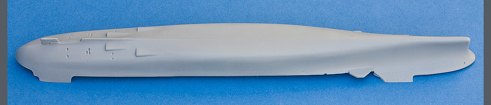
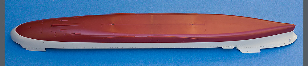
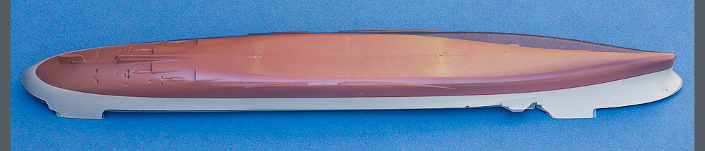
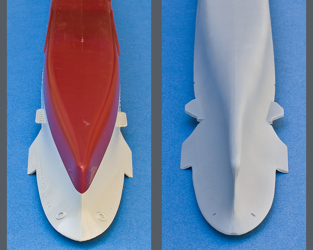
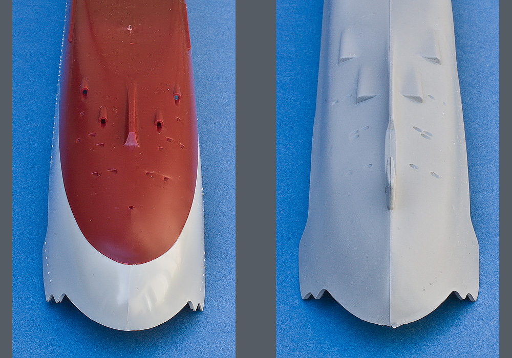
The images below illustrate the differences between the “ancient” Revell Enterprise and the Trumpeter Hornet. I removed the bilge keels from the Revell kit because they were heavily molded in place. This allows better visualization of what the Yorktown hulls are supposed to look like. The third and sixth images have one hull overlaid over the other. It is readily apparent how bulky the Trumpeter bow is. Midship, the Trumpeter hull is flat sided while you can see that the hull actually should curve outward as it approaches the hanger deck. This curve is carried through to the stern and is completely absent in the Trumpeter hull. This curve is readily apparent in any photo of the actual ship and really needs to be considered as a prominent feature. Also note the difference in the exit points for the screw shafts.
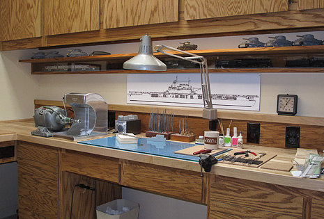
Past experience has shown me that many times it is easier, more accurate, and certainly more rewarding to start from scratch rather than correct major shape issues. I have cleared the workbench and resolved to resist the temptation of becoming distracted by other projects.
I based my construction on two sets of drawings that I ordered from Floating Drydock. Plan W-CV5 – USS Yorktown drawn by Peter Heenan and distributed by Web Warships, and TFW – CV6 – USS Enterprise drawn by Tom Walkowoik. The TFW – CV6 set is drawn for Enterprise in 1944, however, the body plan is the original hull with a separate scrap view of the blisters. The TFW body plan is drawn with 48 stations and describes the hull fore and aft of the perpendiculars. The body plan of the Webb drawing is drawn with only 20 stations and does not include stations forward of the FP, however, it does include lines for the 5” galleries which are not present on the TFW body plan. The Webb drawing does include half-breadth (waterlines) and sheer (buttock lines) plans, however by my measurement, the spacing appears to be irregular. What this all means is that it was necessary to piece together bits from both sets of drawing to get all the information for the hull shape. I relied on the Webb set for general arrangement information because I was doing the Enterprise in 1942.
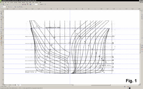
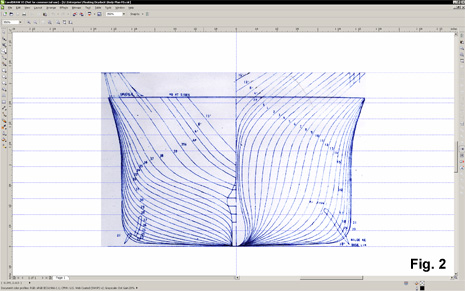
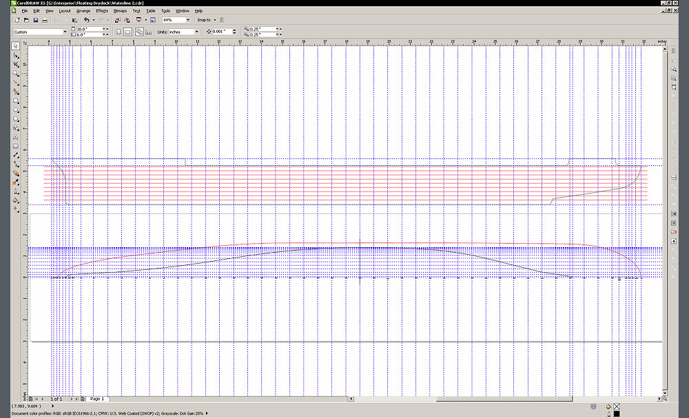
I made the decision to construct a bread and butter waterline hull with 3/16” lifts so I had to draw my own waterlines. While this process can get tedious, it is not difficult. The first step is to collect all the points of intersection. I did this by scanning in the body plan drawings. The drawings were brought into CorelDraw and sized. You can see the irregular spacing of the lifts in the Webb drawing Fig. 1. The Web lifts are numbered while the 3/16” lifts are indicated by the blue guidelines. The TFW body plan is in Fig. 2. Note how many more stations are provided.
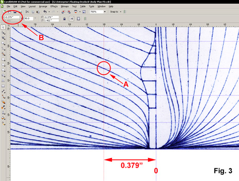
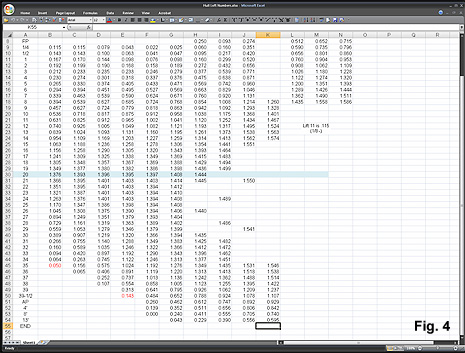
Using guidelines in Corel, it is easy to measure the widest portion of each lift at the various stations. Figure 3 shows the intersect point, A, between the vertical guideline and the widest portion of the lift at a specific station. For most of the stations, the widest portion will be located at the top of the lift, but at the bow, the hull tapers inward from the keel so the widest portion may be found at the bottom or center of the lift depending on the thickness of the lift that you are using. The measurement of the vertical guideline position can be read off in the interactive portion of the toolbar, B. The measurements were recorded in a spreadsheet, Fig. 4.
I made up waterline templates for the TFW and Webb spaced stations. Vertical guidelines lay out the station spacing, while the horizontal lines correspond to the intersections measured in the previous step. I have a sheer outline above marked off with the lift heights. The red waterline is taken directly from the Webb drawing main deck outline. The bezier tool is used to draw a waterline with the points located at the corresponding intersections. With Corel, I first just dropped a point at each intersection. After the line was complete, I selected all the nodes and changed them to a curve, then made them symmetrical and finally selected smooth. At this point, you need to exercise a bit of personal judgment because the bow and stern lines may need a bit of touch up. This is lift #2 from the TFW body plan.
I brought the corresponding TFW and Webb lines together for comparison and made adjustments were necessary to bring them into agreement. The originals were laid out prior to CAD so a bit of modern day “French curve application” is in order. As an aside, I have long since lost my slide rule, but I still have my drafting machine and French curves. The final waterlines are shown below.
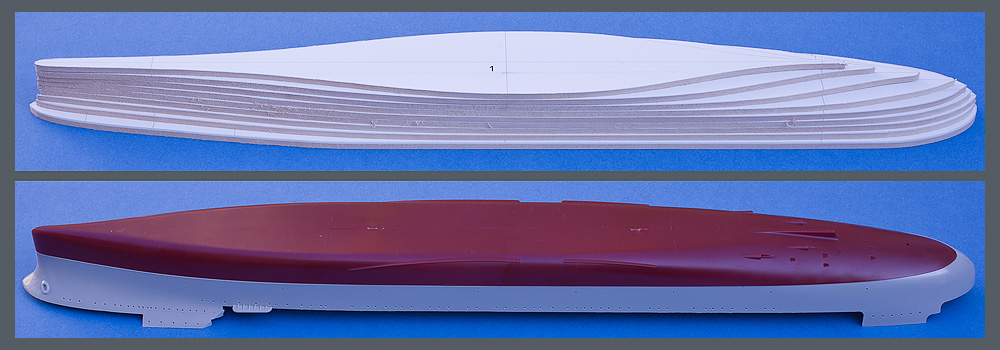
The lifts have been cut from 3/16 basswood. Even at this stage, a comparison against the Trumpeter hull reveals a significant difference.
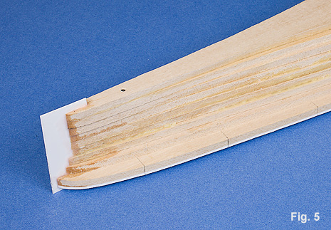
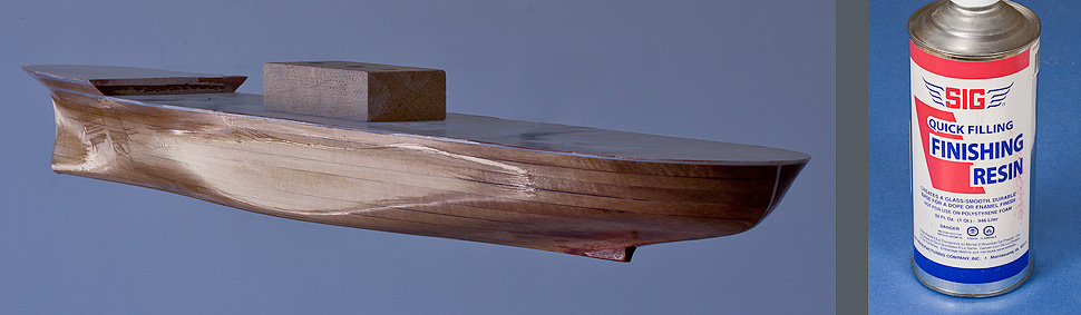
With the exception of the forecastle deck, all the lifts have been glued up. Once the lifts were glued up, a vertical cut was made along the centerline at the bow and the stern, into which a piece of .040” styrene was cemented, Fig. 5. This will provide a nice solid centerline while shaping the hull.
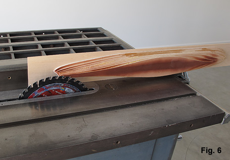
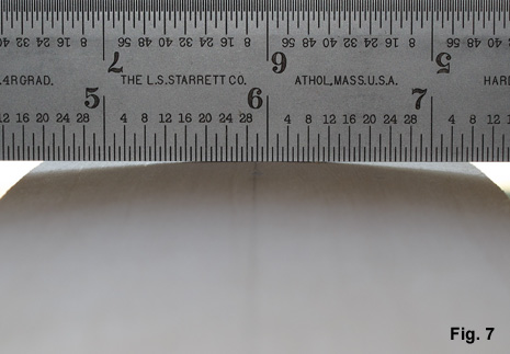
The hull was mounted on a board so that it could be run through the table saw to shape the dead-rise, Fig. 6, 7. A little red primer helps visualize the removal of the material and confirm the maintenance of the keel. The Trumpeter hull bottom is flat, while the Revell hull nicely represents the dead-rise. Chalk another one up for the Revell craftsmen.
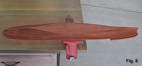
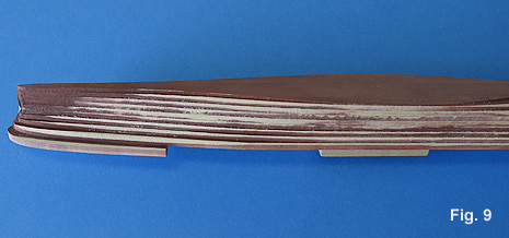
The forecastle deck is attached, let the fun begin, Fig. 8. Note how the red primer helps visualize the material removal, Fig. 9.
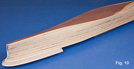
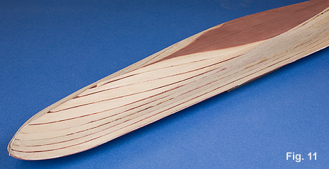
Initial roughing out with various sizes of half-round bastard files, Fig. 10, 11.
Final shaping was done with smooth files and sandpaper. The hull was given several coats of polyester resin.
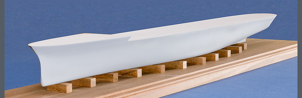
This is the first coat of primer to check for necessary refinements. Hull has been mounted on a mahogany base.
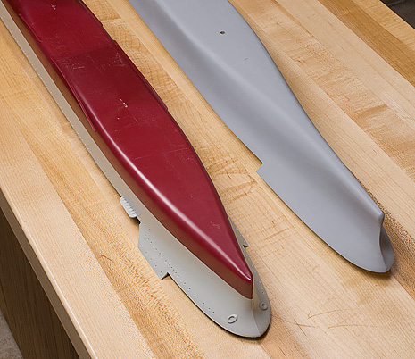
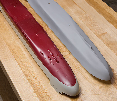
Here is the comparision between the scratch built hull and the Trumpeter hull. I think the differences are striking and worth the effort.
A PDF with the waterlines that I have drawn for this project can be found here. As best I could, I took off the hull plating from the drawings in the Maryland Silver Enterprise book. A PDF of my drawing can be found here. They are for non-commercial use only and I would ask that you do me the favor of crediting their origin.